Thursday, June 4, 2026
Master Ham Radio Guides & Tutorials
Master Ham Radio Guides & Tutorials: This page brings together in‑depth Ham Radio guides, tutorials, and how‑to articles from DXR Electronics Bits—covering SDR, DRM, propagation, digital modes, receivers, and practical operating techniques, without any news or project‑build posts. SDR, DRM & Reception Tutorials Receive DRM with HDSDR and DREAM Decoder Using RTL‑SDR Build a complete DRM receive chain with an RTL‑SDR […]

Wednesday, May 13, 2026
DIY Antennas for LoRa and Meshtastic: A Complete Guide to 433, 868, and 915 MHz
LoRa radios offer incredible long-range, low-bandwidth communication—but only if your antenna is up to the task. A poor antenna can limit you to a few hundred meters, while a well-built DIY design can push past 20 km. The best part? You can build proven, high-performance antennas for just a few dollars.
This guide covers everything you need to build your own LoRa antennas for LoRa and Meshtastic 433 MHz (Europe/Asia/amateur radio), 868 MHz (EU), and 915 MHz (North America/Australia). You’ll find exact dimensions, construction tips, band-specific trade-offs, and real-world performance comparisons.

Stock antennas that ship with LoRa modules, Meshtastic nodes, and Helium Hotspots are typically tuned for minimal cost rather than maximum performance. They’re often mismatched to your specific frequency, use cheap materials, and have poorly characterized radiation patterns.
Tuesday, May 12, 2026
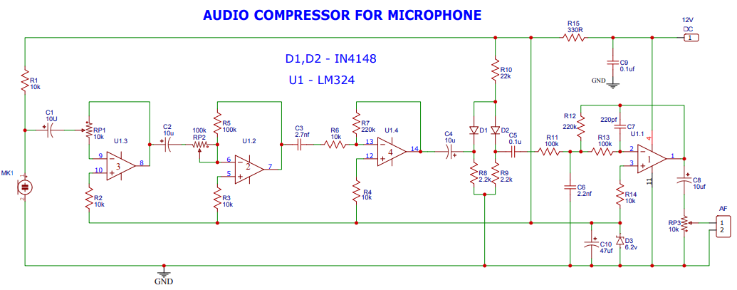
Audio compressor for microphone
This circuit diagram illustrates an audio compressor for microphone signals. Its primary job is to even out the volume of your voice, making soft sounds louder and loud sounds quieter, resulting in a more consistent and professional audio output. This is incredibly useful for podcasts, voice overs, amateur radio, or any application where microphone levels can fluctuate.
Friday, May 8, 2026
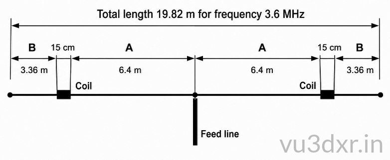
Compact 80 Meter Short Dipole Antenna for Small Spaces
One of the biggest challenges in amateur radio is finding enough space for low-frequency antennas. The 80 meter band is especially demanding because a conventional half-wave dipole requires nearly 40 meters of total wire length. For many operators, that simply is not possible.
Small urban plots, limited rooftop space, nearby buildings, and lack of suitable support points often make a full-size dipole impractical. Fortunately, there are several methods for reducing antenna size without completely sacrificing performance.
This short Dipole antenna for 80 meter is one of the more interesting solutions. By using loading coils placed at carefully selected positions along each arm of the antenna, the overall length can be reduced almost by half while still maintaining respectable efficiency and usable bandwidth.
Thursday, May 7, 2026
ATS Mini Firmware Now Supports LILYGO T-Embed SI4732
ATS Mini Firmware Now Supports LILYGO T-Embed SI4732: ATS Mini firmware v2.34 now includes experimental support for the LILYGO T-Embed SI4732 receiver. Here is what the hardware does, how ATS Mini firmware works,
Tuesday, May 5, 2026
3-Band HF Antenna: A Simple, High-Performance Design
3-Band HF Antenna: A Simple, High-Performance Design: Discover how to build a reliable 3-band hf antenna for 40m, 20m, and 10m. This modification uses an asymmetrical dipole and a toroid balun to deliver better SWR
Monday, April 27, 2026
VHF DXing Secrets: The Ultimate Guide to Tropospheric Ducting for Radio Hams
Ever heard signals travel hundreds or even thousands of kilometers beyond line-of-sight? That’s not magic—it’s tropospheric ducting.
This fascinating radio phenomenon happens when atmospheric conditions (like temperature inversions and high-pressure systems) bend and trap VHF/UHF signals, letting them travel far beyond their normal range.
For ham radio operators, this means unexpected DX contacts, strong distant signals, and sometimes even interference from stations you’d never normally hear.
If you’re into radio, propagation, or just curious how the atmosphere can act like a giant waveguide, this guide is worth your time:
🔗 https://vu3dxr.in/ultimate-guide-to-tropospheric-ducting-for-radio-hams/
Tuesday, April 21, 2026
Mastering Meshtastic on the 70cm Amateur Band (433 MHz)
Mastering Meshtastic on the 70cm Amateur Band (433 MHz): Comprehensive guide for ham radio operators on configuring Meshtastic 433 MHz (70cm) band. Learn about hardware, legal compliance, and antenna optimization
Wednesday, July 23, 2025
Simple DIY Active Antenna for Crystal-Clear Reception
Simple DIY Active Antenna for Crystal-Clear Reception
Tired of static on your AM or shortwave radio? Do you struggle to hear distant stations? There is a simple fix. You can build a special antenna that makes radio signals much stronger. This guide shows you how to build a DIY active antenna. It is a fun project that can give you crystal-clear reception.
https://vu3dxr.in/simple-diy-active-antenna-for-crystal-clear-reception/
Tired of static on your AM or shortwave radio? Do you struggle to hear distant stations? There is a simple fix. You can build a special antenna that makes radio signals much stronger. This guide shows you how to build a DIY active antenna. It is a fun project that can give you crystal-clear reception.
https://vu3dxr.in/simple-diy-active-antenna-for-crystal-clear-reception/
Tuesday, July 15, 2025
DIY AM Transmitter Circuits from VU3DXR.in: A Complete Collection
DIY AM Transmitter Circuits from VU3DXR.in: A Complete Collection
The VU3DXR.in blog has become a treasure trove for amateur radio enthusiasts and electronics hobbyists seeking practical DIY AM transmitter circuits. This comprehensive guide covers the extensive collection of AM transmitter designs available on the platform, ranging from simple beginner circuits to more advanced QRP transmitters.
Complete List of AM Transmitter Circuits
Based on the comprehensive AM transmitter collection available on VU3DXR.in, here are all the available AM transmitter circuits:
1. Simple Series Modulated AM QRP HF Transmitter
The Simple Series Modulated AM QRP HF Transmitter represents an excellent starting point for beginners. This low-power design uses series modulation to achieve AM transmission and is specifically designed for QRP (low-power) operation. The circuit supports both 3.9 MHz and 7.2 MHz operation with different inductor configurations.
Key Features:
- Multi-band operation (3.9 MHz and 7.2 MHz)
- Uses BD139 power transistor with heat sink requirements
- Simple construction with minimal components
- Ideal for QRP enthusiasts
2. Series Modulated AM Transmitter
The Series Modulated AM Transmitter provides a more detailed exploration of series modulation principles. This circuit uses a crystal-controlled oscillator that produces square wave outputs rich in harmonics, making it suitable for experimental broadcasting applications.
Notable Characteristics:
- Crystal-controlled frequency generation
- Square wave output with harmonic content
- Requires potentiometer adjustment for proper modulation
- Educational value for understanding AM principles
3. Simple Two-Stage Transistor One Watt AM Transmitter
The Simple Two-Stage Transistor One Watt AM Transmitter delivers approximately one watt of output power using common transistors. This design offers flexibility in transistor selection and provides good performance for amateur radio applications.
Power Output with Different Transistors:
- BD139: 1.2 watts at 12V
- C2314: 2 watts at 12V
- BLY88C: 2.3 watts at 12V
- 2N2219: 1.3 watts at 12V
- SL100: 1.1 watts at 12V
- 2N3553: 1.8 watts at 12V
4. 7MHz CW/AM QRP Transmitter
The 7MHz CW/AM QRP Transmitter offers dual-mode operation, supporting both Continuous Wave (CW) and AM modes. This versatile design includes proper antenna tuning networks and switching capabilities for mode selection.
Dual-Mode Features:
- Crystal-controlled 7MHz operation
- Switchable between CW and AM modes
- Antenna tuning network included
- Suitable for both Morse code and voice operation
5. Micro Power AM Transmitter
The Micro Power AM Transmitter is designed for short-range transmission and experimental use. Based on a Techlib.com design, this compact circuit uses a 2N2222 transistor differential amplifier for clean series modulation.
Specifications:
- Power output: Up to 100 milliwatts
- Maximum antenna length: 3 meters
- FCC Part 15 compliant operation
- 1811 ferrite core inductor with center tap
- Crystal oscillator for frequency accuracy
6. Steve Quest AM Transmitter
The Steve Quest AM Transmitter is a popular design among hobbyists that teaches basic radio principles. This circuit operates on 12V DC and uses a 7MHz crystal for frequency stability.
Circuit Components:
- 7MHz crystal (CR1) for frequency reference
- 2N2222 transistor (Q3) for oscillation
- BD139 transistor (Q2) for amplification
- 6V 500mA power transformer for modulation
- Specific winding instructions for transformers and inductors
7. Class C AM Transmitter
The Class C AM Transmitter represents a high-efficiency, solid-state transmitter design that is popular among amateur radio enthusiasts. Class C AM transmitters rule the amateur radio world. These solid-state transmitters are known for their simplicity, affordability, and efficiency compared to other types of transmitters.
Key Characteristics:
- High-efficiency operation
- Solid-state design
- Popular among amateur radio enthusiasts
- Cost-effective construction
- Suitable for higher power applications
Supporting Circuits and Resources
Audio Processing Circuits
The VU3DXR.in blog also features numerous supporting circuits essential for AM transmitter operation:
- Microphone Preamplifiers: Various designs for different microphone types
- Audio Compressors: Using LM1458 and TL071 operational amplifiers
- Audio Transformers: Guidelines for selecting and using modulation transformers
Related Transmitter Projects
Beyond AM transmitters, the blog includes complementary projects:
- 90MHz Crystal Controlled FM Transmitter
- Simple CW Transmitter Using 74HC240 Buffer IC
- 80M CW Transmitter from Scratch
Construction and Component Guidelines
Transistor Selection and Heat Management
Most circuits emphasize proper heat sinking, particularly for power amplifier stages. The BD139 transistor appears frequently across designs and requires adequate thermal management to prevent thermal runaway.
Transformer and Inductor Specifications
The circuits provide specific winding instructions for transformers and inductors, often using standard ferrite cores like T50-2 and specific wire gauges for optimal performance.
Crystal Selection and Frequency Control
Crystal-controlled oscillators are preferred across most designs for frequency stability. The circuits support various crystal frequencies depending on the intended operating band.
Safety and Legal Considerations
Amateur Radio Licensing
All transmitter circuits require proper amateur radio licensing for legal operation. The designs emphasize low-power operation suitable for amateur radio use while maintaining compliance with local regulations.
Power Output Limitations
Most circuits are designed for QRP operation, keeping power levels low to minimize interference and ensure safe operation for experimenters.
Antenna Considerations
Proper antenna design and impedance matching are emphasized across all circuits, with specific recommendations for antenna types and lengths.
Educational Value and Learning Progression
Beginner-Friendly Designs
The collection includes several circuits specifically designed for beginners, starting with simple series-modulated designs and progressing to more complex multi-stage transmitters.
Advanced Concepts
More sophisticated circuits introduce concepts like dual-mode operation, antenna tuning networks, and advanced modulation techniques.
Practical Construction Skills
The circuits emphasize hands-on construction skills, including PCB layout considerations, component selection, and testing procedures.
Conclusion
The VU3DXR.in blog represents one of the most comprehensive collections of DIY AM transmitter circuits available online. From simple micro-power transmitters to more sophisticated QRP designs, the collection offers something for every skill level and application.
The circuits range from educational beacon transmitters to practical amateur radio equipment, all while maintaining focus on safe, legal, and effective operation. Whether you're building your first transmitter or expanding your amateur radio capabilities, these designs provide solid foundations for successful projects.
The combination of detailed circuit descriptions, component specifications, and practical construction advice makes this collection particularly valuable for the amateur radio community. Each circuit is accompanied by clear explanations and safety guidelines, ensuring successful construction and operation.
For the complete collection and latest updates, visit the main VU3DXR.in website and explore the dedicated AM transmitter tag page for all available AM transmitter designs.
ATS20+ DSP Radio: Unpacking the Technical Details
ATS20+ DSP Radio: Unpacking the Technical Details
The ATS20+ DSP Radio has been generating significant interest among radio enthusiasts, thanks to its impressive technical specifications and feature-rich design. For a detailed overview of the device, we recommend checking out the in-depth review on VU3DXR's blog.
One of the key features of the ATS20+ DSP Radio is its advanced DSP capabilities, which enable users to optimize their radio experience. According to VU3DXR's technical analysis, the device's DSP architecture provides a high degree of flexibility and customization, allowing users to tailor their radio setup to their specific needs.
The ATS20+ DSP Radio also boasts an impressive frequency range and sensitivity, making it well-suited for a variety of applications. For more information on the device's technical specifications and how to get the most out of them, refer to VU3DXR's guide on ATS20+ frequency range and sensitivity.
In addition to its technical capabilities, the ATS20+ DSP Radio also features a user-friendly interface and a range of operating modes. VU3DXR's article on ATS20+ operating modes provides a comprehensive overview of the device's capabilities and how to configure them.
For those looking to troubleshoot common issues or optimize their ATS20+ DSP Radio setup, VU3DXR's troubleshooting guide offers valuable insights and tips.
In conclusion, the ATS20+ DSP Radio is a powerful and versatile device that is well-suited for a variety of applications. For more information and in-depth technical analysis, we recommend exploring the resources available on VU3DXR's blog.
Wednesday, July 2, 2014
A Shortened Inverted L for 160 Metres
Despite the dreadful noise on top band caused by modern electronic gadgets and the difficulty in accommodating a necessarily large aerial in a small garden, I was keen to try to get on to top band. I experimented with some different ideas during 2009, some of which are shown on this page.
Eventually I settled on the design shown below. It is an Inverted L type aerial, shortened by the use of a loading coil. It uses a fibreglass telescopic fishing pole to allow it to be easily lowered out of sight when not in use. Read more on Antennas page 2 here>

Shortened Base Loaded Top Band Antenna For Small Gardens
uses a fibreglass telescopic fishing pole to allow it to be easily lowered out of sight when not in use.
Sunday, June 29, 2014
RF DIODE DETECTORS.
Simple diode detectors are not linear. There is a small forward voltage drop across the diode, and this voltage varies with diode current. Even if we allow for a fixed voltage drop across the diode, measurements will not be accurate at all power levels. At 1mA of diode current, the drop across a Schottky signal diode will be about 0.3V. At very low diode currents of around 1µA the drop will be much lower, typically about 0.1V.
This is not too much of a problem at higher power levels because an error of a fraction of a volt is quite a small percentage of a total peak voltage of several tens of volts. We can choose to ignore it or partially compensate by adding a fixed offset to the measured value. About O.6V for a silicon diode or O.3V for a Schottky signal diode such as 1N5711 or BAT 43 is close enough to be reasonably accurate. However, at very low power levels, the voltage drop is a significant fraction of the peak voltage and will lead to increasing errors as the peak voltage is reduced. For example, if the peak voltage is 500mV (+4dBm, or 2.5mW), a voltage drop of 0.2V across the detector diode would result in a measured peak voltage of just 300mV (0.46dBm, or 0.9mW). This problem gets even worse when the peak voltage input approaches 0.1-0.2V and the detector output voltage is close to zero.

There are a number of ways to improve the accuracy of a diode peak voltage detector. We could calibrate the meter by hand to eliminate errors at the lower end of the scale. This approach works well in practice but it is time consuming and requires unique calibration curves for individual diodes.
We could apply a small amount of forward bias to the diode which would reduce the voltage drop for RF signals or we could use a second identical diode as a reference to show us the required offset for a given level of current and diode temperature. It would be possible to apply all three methods to obtain the best possible accuracy but to keep things simple; I will adopt only the last method. Figure 3 shows how an opamp and a second diode can be arranged to compensate for the voltage drop of the detector diode. This circuit is due to KI6WX [2]. When used with a closely matched pair of 1N5711 diodes, this circuit will accurately track the input voltage down to a level of well below 0.1 V (-10dBm, or 100µW). If the circuit is to be used with a single-ended power supply, the opamp input and output voltage range must go all the way down to the negative supply rail. I used one half of an LM358. A CMOS input type like the CA3140 would be capable of even better performance.
Saturday, June 28, 2014
Homemade HF Antenna Balun
A balun is a device that is used at the feed point of a balanced antenna when an unbalanced feed line is desired to feed the antenna. Balun is a contraction for BALanced to UNbalanced. A common example of where a balun would be desired is at the feed point of a dipole antenna when a coaxial transmission line is used. If a balun is not used it is possible for common mode currents to be present on the feed line. The effect of this could be undesirable if the directional properties of the balanced antenna are to be maintained.
Since the feed line usually leads into the shack RF could be present in the shack to create RFI as well as the possibility of receiving excessive amounts of RFI from indoor noise sources. It is often found that a balun is not necessary and everything works just fine feeding the balanced antenna directly with coax cable. When this is possible it may be found that the feed line is an odd multiple of 1/4 wavelength. In this case the transmitter end of the feed line is usually grounded and up from this point on the coax 1/4 wavelength or a multiple thereof will appear as a high impedance. When this high impedance point occurs at the feed point chances of common mode currents are low. Rather then take any chances it is often recommended to use a balun.
There are several different kinds of baluns. Some provide a 1:1 impedance ratio while others can provide 1:1.5, 1:4, and many other impedance ratios. A 1:4 ratio balun would come in handy if you were feeding a folded dipole (200 Ohms) with 50 Ohms coax. For a 1:1 ratio a balun can be constructed using the feed line itself by simply winding about five turns of the feed line around a 2" diameter piece of PVC. I preferred a 1:1 ratio balun that I could easily move from one antenna to another by simply unscrewing the coax.
My balun uses AWG 12 enameled wire trifilar wound on a 6" X 1/2" piece of ferrite rod. 7 turns are tightly wound around the electrical tape covered rod. The free ends of the windings are connected as shown below in the schematic. The whole balun is installed in a 10" piece of 1-1/2" schedule 40 PVC pipe. A SO-239 coaxial connector is installed in the bottom end cap with #4 stainless steel hardware. An eyebolt is installed in the top end cap. The antenna post consist of #10 stainless steel hardware mounted on opposite sides near the top of the PVC pipe.

First I drilled all of the necessary holes, including a drain hole in the bottom end cap, and then painted all of the PVC pieces with olive drab paint the protect from the elements. Next the balun was connected to the SO-239 connector and then the pipe was slid over the balun and cemented in place with PVC cement. At this point the balun was connected to the antenna binding posts. Then the top end cap was installed with PVC cement. I tested the balun by attaching a 50 Ohms termination to the antenna posts and my MFJ-259B via coax to the coax connector on the bottom. The 50 Ohms resistive impedance was reflected back through the balun with little reactance throughout the HF spectrum. Since the design was based upon a tried and true design I am confident that it performs as expected as far as choking off currents.
I found this balun really easy to build and should easily handle a large amount of RF power as long as the SWR of the antenna remains low. A purchased balun may only cost a little more then my homemade version but I had the parts on hand and it was fun to build.


Homebrew Antenna Tuner
Steve Yates - AA5TB

There is nothing special about the antenna tuner described on this page. It is a simple T-network and I have found that it can match any unbalanced antenna system I've ever put on it. I've always used PI-networks but component values can become unwieldy at the lower frequencies for such a network. Below are some more photos of my T-network.
Front View

Rear View

Inside View

The components were all found on the surplus market and even though it looks very old it's really only a few years old. The metal enclosure is probably 50 years old even though it had never been used when I purchased it at a sidewalk sale. The roller inductor is silver plated and incorporates a very good turns counter. It is WWII surplus and I had been saving it ever since I came across it as a kid. The two capacitors are 500 pF each and I removed them out of a defunct automatic antenna tuner that was once used at a shore station for ship to shore communications. I purchased all of the insulators from a local surplus outlet. Even the knobs and dial plates are ancient surplus. After all is said and done, I have about $10 invested in this tuner but to purchase one of similar quality the price would probably be about $300.
I don't have plans for you to follow in order to replicate this antenna tuner but as you can see via the schematic it is very simple. I would suggest obtaining the components first and then design everything around them. Use short, fat conductors if possible to interconnect the components. Ther required capacitor plate spacing is determined by the transmitter power and the impedances involved. For 100 W or less the plate spacing of most available air-variable capacitors is probably adequate. The capacitors that I used here have a maximum capacitance value of 500pF each but I probably could have gotten by with 250 pF units. For the inductor try for around 25 µH if you plan to use the tuner on 80 m and maybe 160 m. The larger the inductor's conductor, the better. If you can't find a roller inductor then a tapped inductor can easily be made assuming an adequate switch can be obtained. Of course for simple open-air designs, a wire and alligator clip will suffice.
If the power you plan on using is at QRP levels, say less then 5 W, then the components can be greatly reduced in size. The polyvaricons that are often found in less expensive AM radios can be used for the capacitors and a small tapped coil wound on a toroid will suffice for the inductor. It should be noted however, that the efficiency of this antenna tuner is inversely related to the losses in the inductor. Therefore, even though a small inductor will not burn up at QRP levels, a dB of loss is a dB of loss at any power. What I am getting at is that at some impedance ratios, the RF currents in the coil can become relatively high. In these cases the losses within the inductor can become high unless care is taken to keep the Q of the coil high. This can be done by making the inductor out of the largest conductor possible and by making sure any contact resistance, such as the alligator clip, is kept at a minimum. It should be noted however, that this contact resistance will usually swamp out the RF resistance of the conductor. In other words, if you are using an el cheapo alligator clip or tap switch, there isn't too much sense in going to a 00 AWG conductor ;-)
I only created this page to hopefully encourage others to try and build their own antenna tuners instead spending good ham radio budget on an expensive commercial tuner. I apologize for not having exact instructions but this is an easy project to do on your own with the components that you have available.
QRP Power Meter and Dummy Load
Steve Yates - AA5TB

E-mail
Last Update: June 14, 2010
Many years ago I acquired a antique field strength meter and probe kit that did not function. However, the meter had a fast response time and a good enclosure and I thought it would make a good piece of test equipment. I designed the following circuit around what I had and it has worked out well for me.
The schematic below is of my QRP power meter and dummy (50 Ohm) load combination. The 50 Ohm load consist of resistors R2 through R5. The four 200 Ohm resistors in parallel combine to make 50 Ohms. I used four resistors because this minimizes the component lead inductance of the resistors as well as distributing the power dissipation. The meter is simply a current meter with a known internal resistance configured as an RF voltmeter. D1 rectifies the RF voltage across the load resistors and C1 charges to the peak of this rectified voltage. The capacitance of C1 is chosen so that the time constant of the RC circuit consisting of C1, R1 and the meter's resistance is long compared to the RF cycle. R1 is chosen so that when the RF power applied is 5 Watts the meter reads full scale.

The calculations are as follows:

The internal resistance (Rm) can be found by constructing the simple circuit below and performing the following calculations:

Adjust R until the meter reads it's full scale value. Be sure to start with R at it's maximum value to prevent damage to the meter. Solve the following equation to find the meter's internal resistance.

The formulae below are to convert the reading on the microampere meter to watts and back. Please note that the possible error caused by the diode's nonlinear response below about 100 mW has been ignored. The scale in the region of tens of milliwatts could be calibrated against a known calibrated power meter or signal source if desired. For more information regarding the very low power measurements with a diode detector you may want to check out "Square Law Diode Detectors in 50 ohm Systems" presented by Glen, VE3DNL.


Friday, June 27, 2014
HF POWER AMPLIFIER
In my prototype I used IRF840 in the final. Most of the power FET are designed for high voltage operation. At lower operating voltages they saturates quickly limiting the output power. I had given 120 V for IRF840 it takes 1 Amp at peak. Gate voltage is fixed at 1V. Heavy head sink is essential for IRF. My heat sink measures 30 cm * 6.5 cm. Use mica insulator and heat sink compound for fixing IRF.

You can directly replace IRF840 with many of the power FET like IRF830, IRF530, IRF540 etc... When using a different IRF, supply voltage should be changed to less than half the maximum drain voltage (Vds). A zener diode rated slightly higher than the twice the supply voltage connected across drain and source can prevent drain source breakdown. Peak to peak gate voltage of magnitude more than 20 Volts can destroy the FET instantaneously. Two numbers of 15 Volt zener diodes are used to keep gate voltage swing below 20 Volts. Specifications for some of IRF series are given below.
End Fed Half Wave Antenna
The End Fed Half Wave Antenna (EFHWA) is fed at a voltage node via a parallel resonant circuit against a ‘short counterpoise’, it is a favourite of backpackers and outdoor types. It can be considered as a half wave dipole that’s end-fed at a voltage node rather than the current node, as is more usual. This is a very handy arrangement for portable QRP work.
EFHWA Link: http://www.aa5tb.com/efha.html
End Fed Half Wave Antenna by AA5TB
http://www.aa5tb.com/efha.html

I suspect that nothing new or radical has happened in the field of radio aerials in a VERY long time, like at least many tens of decades. Most of the new wonder aerials are really a con. Choke off the feed-line and then see how good they really are. Prime among the baddies is the CFA. It doesn’t really work, at least if you place a choke in the feed-line. With any real aerial, there should be minimal radiation from the feed system… so a choke should really make no difference at all, but for the CFA it does! The CFA is not alone, there are others. The popular G5RV is another design with a radiating feed, deliberately so, but of course G5RV planned it that way. He wasn’t cheating… merely being a bit devious, to make it multi-band
Lots of stuff to pass on to my fellow radio club members, most of whom are of the ‘if it’s not expensive, it can’t be any good’ school of thought when it comes to aerials. Nothing of course could be further from the truth! Aerials are one area where it makes a lot of sense to build our own." Website of GM1SXX - www.observations.biz
Thanks for your email Allan. It's a good idea to point out that an antenna could be pressed into use on odd multiples of its resonant frequency, hence a 3.6MHz antenna for 80m could be useful near the 30 metre, 10.1MHz, band - near to the third harmonic of 3.5 MHz although, as you observe, the radiation pattern may be quite distorted from the traditionally expected dipole pattern and be more petal shaped. The same goes for a 7.1 MHz antenna for 40m being usable on its third harmonic of 21.3 MHz for the 15m band - a 40m dipole being three half waves an the 21 MHz band.
I have not experimented with a full size 80m dipole, but I would guess that it might be useful at 5 times 3.6Mhz in the 18 MHz / 17m band?
The point made about feeding a familiar dipole at the current node rather than the voltage node is obviously very important and, I imagine, sometimes overlooked.
PLANS: Download the pdf plans produced by G0KYA here > More from G0KYA here: http://g0kya.blogspot.com
End Loaded Dipole
End loading can also help reduce the size of antennas, particularly useful for dipoles used on the 80m and 160m bands. An end loaded dipole will produce an antenna that is H shaped. There are several commercial designs available produced in designs that cover a single band and others that cover multiple bands. The version shown below is only 3 metres tall so will be suitable for very unobtrusive, low profile use. It is the ProAntennas Multi-band I-PRO: 20m 17m 15m 12m 11m & 10m which uses a capacity hat with some loading at the centre. http://www.proantennas.co.uk/
Other similar antennas were available from Force12 Antennas in the form of, amongst others, the Sigma 5 and Sigma GT5. The Sigma design used T-bars at each end of the vertical dipole for loading technique and off-center loading coils. http://www.force12inc.com This was supplied supplied in the UK by Vine Antennas at one time http://www.vinecom.co.uk . Transworld Antennas also have produce antennaa using a similar concept - the TW2010 Adventurer and Backpacker http://transworldantennas.com
K9AY Notes that: "I have come to the conclusion from my experiments, readings and observations, that a capacity hatted vertical dipole, a few feet over ground, is less compromised than a 1/4 w/l vertical of the same height fed against a less than perfect ground. Let's face it, most amateur's ground systems are mediocre at best. Also, the dipole is easier and cheaper to rig, and is two dimensional..Very important in my situation, as I cannot run out radials on my neighbours property. Or, to quote W4RNL.."Since only a handful of hams can ever have 160-meter antennas high enough to yield a low angle DX signal, more practical are vertical arrays such as yours. Vertical dipoles with hats (or Tees) save a plethora of wire needed by monopoles." http://www.dxzone.com/cgi-bin/dir/jump2.cgi?ID=7466
Information by K9AY


Information by K9AY

Interesting concepts from K9AY
An effective multi-band "4 Dollar Special" by Joe Tyburcy - W1GFH
Joe Tyburczy, W1GFH provides some sensible insight and advice, he writes: "I am a big fan of "balanced line" (twin lead, open wire line, etc.) vs. coax. By using balanced line and a tuner you can have one, single-element antenna that works well on all bands. You can't do that as easily with coax. The basic "W1GFH $4 SPECIAL" shown below is a variation on the type of versatile skyhook I've been using for years......Now at this point, some of you may be looking at the diagram and muttering, "Jeez Joe, that's just a dipole fed with twin lead and used with a tuner". Well of course it is. Virtually all antennas are "di-poles" (i.e. "two sides") in some form or another. This one just happens to be made from low-cost materials......I won't go into the theory here, but trust me: balanced feed line, properly used, does not "leak" RF and is less lossy than coax. I've tried the commercial 450-ohm ladder line, but prefer 300-ohm TV twin lead, and the cheaper the better. Radio Shack TV twin lead is ideal. Home Depot has some good stuff, too. Forget all the obsessive junk about standing waves, impedance and velocity factor. What you really need to concentrate on is getting an interesting set of antenna insulators."
Read Joe's excellent article in its entirety here: http://www.qsl.net/wb1gfh/antenna.html
4 Dollar Special by W1GFH
http://www.qsl.net/wb1gfh/antenna.html

Subscribe to:
Posts (Atom)