Wednesday, July 2, 2014

A Shortened Inverted L for 160 Metres


Despite the dreadful noise on top band caused by modern electronic gadgets and the difficulty in accommodating a necessarily large aerial in a small garden, I was keen to try to get on to top band. I experimented with some different ideas during 2009, some of which are shown on this page.

Eventually I settled on the design shown below. It is an Inverted L type aerial, shortened by the use of a loading coil. It uses a fibreglass telescopic fishing pole to allow it to be easily lowered out of sight when not in use.  Read more on Antennas page 2 here>

Top Band Inverted L Aerial - shortened for small gardens - by M0MTJ

Shortened Base Loaded Top Band Antenna For Small Gardens
uses a fibreglass telescopic fishing pole to allow it to be easily lowered out of sight when not in use.

Sunday, June 29, 2014

RF DIODE DETECTORS.

Simple diode detectors are not linear. There is a small forward voltage drop across the diode, and this voltage varies with diode current. Even if we allow for a fixed voltage drop across the diode, measurements will not be accurate at all power levels. At 1mA of diode current, the drop across a Schottky signal diode will be about 0.3V. At very low diode currents of around 1µA the drop will be much lower, typically about 0.1V.

This is not too much of a problem at higher power levels because an error of a fraction of a volt is quite a small percentage of a total peak voltage of several tens of volts. We can choose to ignore it or partially compensate by adding a fixed offset to the measured value. About O.6V for a silicon diode or O.3V for a Schottky signal diode such as 1N5711 or BAT 43 is close enough to be reasonably accurate. However, at very low power levels, the voltage drop is a significant fraction of the peak voltage and will lead to increasing errors as the peak voltage is reduced. For example, if the peak voltage is 500mV (+4dBm, or 2.5mW), a voltage drop of 0.2V across the detector diode would result in a measured peak voltage of just 300mV (0.46dBm, or 0.9mW). This problem gets even worse when the peak voltage input approaches 0.1-0.2V and the detector output voltage is close to zero.

 image 16

There are a number of ways to improve the accuracy of a diode peak voltage detector. We could calibrate the meter by hand to eliminate errors at the lower end of the scale. This approach works well in practice but it is time consuming and requires unique calibration curves for individual diodes.

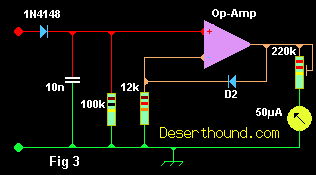
We could apply a small amount of forward bias to the diode which would reduce the voltage drop for RF signals or we could use a second identical diode as a reference to show us the required offset for a given level of current and diode temperature. It would be possible to apply all three methods to obtain the best possible accuracy but to keep things simple; I will adopt only the last method. Figure 3 shows how an opamp and a second diode can be arranged to compensate for the voltage drop of the detector diode. This circuit is due to KI6WX [2]. When used with a closely matched pair of 1N5711 diodes, this circuit will accurately track the input voltage down to a level of well below 0.1 V (-10dBm, or 100µW). If the circuit is to be used with a single-ended power supply, the opamp input and output voltage range must go all the way down to the negative supply rail. I used one half of an LM358. A CMOS input type like the CA3140 would be capable of even better performance.

Saturday, June 28, 2014

Homemade HF Antenna Balun


A balun is a device that is used at the feed point of a balanced antenna when an unbalanced feed line is desired to feed the antenna. Balun is a contraction for BALanced to UNbalanced. A common example of where a balun would be desired is at the feed point of a dipole antenna when a coaxial transmission line is used. If a balun is not used it is possible for common mode currents to be present on the feed line. The effect of this could be undesirable if the directional properties of the balanced antenna are to be maintained.

Since the feed line usually leads into the shack RF could be present in the shack to create RFI as well as the possibility of receiving excessive amounts of RFI from indoor noise sources. It is often found that a balun is not necessary and everything works just fine feeding the balanced antenna directly with coax cable. When this is possible it may be found that the feed line is an odd multiple of 1/4 wavelength. In this case the transmitter end of the feed line is usually grounded and up from this point on the coax 1/4 wavelength or a multiple thereof will appear as a high impedance. When this high impedance point occurs at the feed point chances of common mode currents are low. Rather then take any chances it is often recommended to use a balun.

There are several different kinds of baluns. Some provide a 1:1 impedance ratio while others can provide 1:1.5, 1:4, and many other impedance ratios. A 1:4 ratio balun would come in handy if you were feeding a folded dipole (200 Ohms) with 50 Ohms coax. For a 1:1 ratio a balun can be constructed using the feed line itself by simply winding about five turns of the feed line around a 2" diameter piece of PVC. I preferred a 1:1 ratio balun that I could easily move from one antenna to another by simply unscrewing the coax.

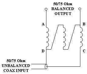
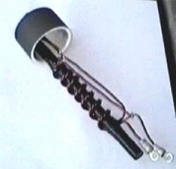
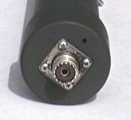
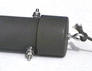
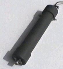
My balun uses AWG 12 enameled wire trifilar wound on a 6" X 1/2" piece of ferrite rod. 7 turns are tightly wound around the electrical tape covered rod. The free ends of the windings are connected as shown below in the schematic. The whole balun is installed in a 10" piece of 1-1/2" schedule 40 PVC pipe. A SO-239 coaxial connector is installed in the bottom end cap with #4 stainless steel hardware. An eyebolt is installed in the top end cap. The antenna post consist of #10 stainless steel hardware mounted on opposite sides near the top of the PVC pipe.

My Balun Schematic

First I drilled all of the necessary holes, including a drain hole in the bottom end cap, and then painted all of the PVC pieces with olive drab paint the protect from the elements. Next the balun was connected to the SO-239 connector and then the pipe was slid over the balun and cemented in place with PVC cement. At this point the balun was connected to the antenna binding posts. Then the top end cap was installed with PVC cement. I tested the balun by attaching a 50 Ohms termination to the antenna posts and my MFJ-259B via coax to the coax connector on the bottom. The 50 Ohms resistive impedance was reflected back through the balun with little reactance throughout the HF spectrum. Since the design was based upon a tried and true design I am confident that it performs as expected as far as choking off currents.

I found this balun really easy to build and should easily handle a large amount of RF power as long as the SWR of the antenna remains low. A purchased balun may only cost a little more then my homemade version but I had the parts on hand and it was fun to build.

Internal View Bottom View Top View Completed Balun


Homebrew Antenna Tuner


Steve Yates - AA5TB

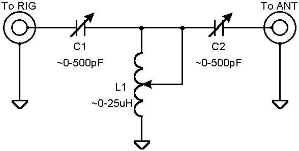
Tuner Schematic


For years I've thrown together simple antenna tuners to get me on the air when needed. Whenever I would go to a sidewalk sale or hamfest I would pick up any components that might someday come in handy to make an antenna tuner. Commercial antenna tuners are very expensive and often of questionable quality. They are so very simple to make that I find it hard to justify purchasing a store bought unit. I realize that good antenna tuner components can be quite expensive when purchased new if you are even lucky enough to find a supplier. If you are not in a hurry all of the necessary components can be found used for very reasonable prices.

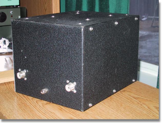
There is nothing special about the antenna tuner described on this page. It is a simple T-network and I have found that it can match any unbalanced antenna system I've ever put on it. I've always used PI-networks but component values can become unwieldy at the lower frequencies for such a network. Below are some more photos of my T-network.
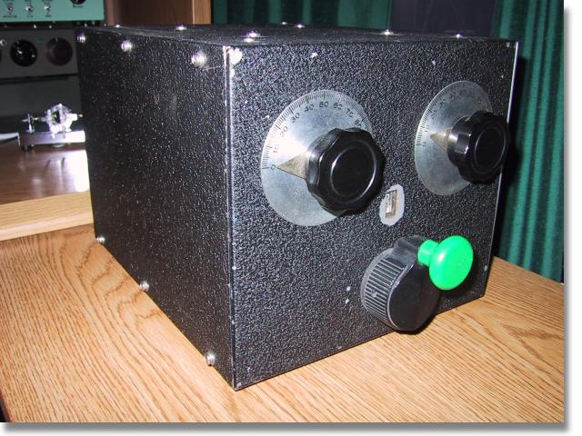
Front View
Front View

Rear View
Rear View

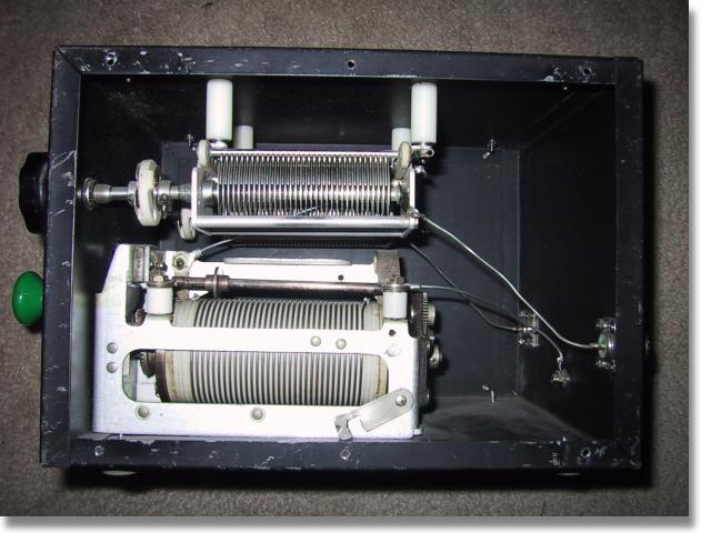
Inside View
Inside View

The components were all found on the surplus market and even though it looks very old it's really only a few years old. The metal enclosure is probably 50 years old even though it had never been used when I purchased it at a sidewalk sale. The roller inductor is silver plated and incorporates a very good turns counter. It is WWII surplus and I had been saving it ever since I came across it as a kid. The two capacitors are 500 pF each and I removed them out of a defunct automatic antenna tuner that was once used at a shore station for ship to shore communications. I purchased all of the insulators from a local surplus outlet. Even the knobs and dial plates are ancient surplus. After all is said and done, I have about $10 invested in this tuner but to purchase one of similar quality the price would probably be about $300.

I don't have plans for you to follow in order to replicate this antenna tuner but as you can see via the schematic it is very simple. I would suggest obtaining the components first and then design everything around them. Use short, fat conductors if possible to interconnect the components. Ther required capacitor plate spacing is determined by the transmitter power and the impedances involved. For 100 W or less the plate spacing of most available air-variable capacitors is probably adequate. The capacitors that I used here have a maximum capacitance value of 500pF each but I probably could have gotten by with 250 pF units. For the inductor try for around 25 µH if you plan to use the tuner on 80 m and maybe 160 m. The larger the inductor's conductor, the better. If you can't find a roller inductor then a tapped inductor can easily be made assuming an adequate switch can be obtained. Of course for simple open-air designs, a wire and alligator clip will suffice.

If the power you plan on using is at QRP levels, say less then 5 W, then the components can be greatly reduced in size. The polyvaricons that are often found in less expensive AM radios can be used for the capacitors and a small tapped coil wound on a toroid will suffice for the inductor. It should be noted however, that the efficiency of this antenna tuner is inversely related to the losses in the inductor. Therefore, even though a small inductor will not burn up at QRP levels, a dB of loss is a dB of loss at any power. What I am getting at is that at some impedance ratios, the RF currents in the coil can become relatively high. In these cases the losses within the inductor can become high unless care is taken to keep the Q of the coil high. This can be done by making the inductor out of the largest conductor possible and by making sure any contact resistance, such as the alligator clip, is kept at a minimum. It should be noted however, that this contact resistance will usually swamp out the RF resistance of the conductor. In other words, if you are using an el cheapo alligator clip or tap switch, there isn't too much sense in going to a 00 AWG conductor ;-)

I only created this page to hopefully encourage others to try and build their own antenna tuners instead spending good ham radio budget on an expensive commercial tuner. I apologize for not having exact instructions but this is an easy project to do on your own with the components that you have available.

QRP Power Meter and Dummy Load


Steve Yates - AA5TB

AA5TB Meter Photo 1

HOME

E-mail
Last Update: June 14, 2010

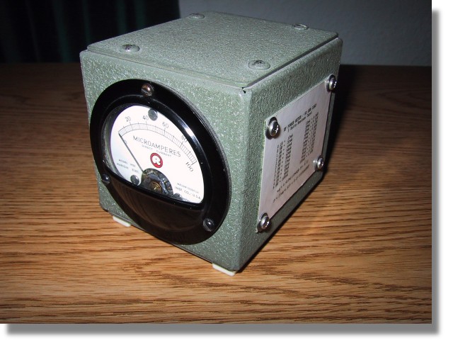
Many years ago I acquired a antique field strength meter and probe kit that did not function. However, the meter had a fast response time and a good enclosure and I thought it would make a good piece of test equipment. I designed the following circuit around what I had and it has worked out well for me.

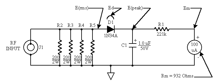
The schematic below is of my QRP power meter and dummy (50 Ohm) load combination. The 50 Ohm load consist of resistors R2 through R5. The four 200 Ohm resistors in parallel combine to make 50 Ohms. I used four resistors because this minimizes the component lead inductance of the resistors as well as distributing the power dissipation. The meter is simply a current meter with a known internal resistance configured as an RF voltmeter. D1 rectifies the RF voltage across the load resistors and C1 charges to the peak of this rectified voltage. The capacitance of C1 is chosen so that the time constant of the RC circuit consisting of C1, R1 and the meter's resistance is long compared to the RF cycle. R1 is chosen so that when the RF power applied is 5 Watts the meter reads full scale.

QRP Power Meter and Dummy Load Schematic

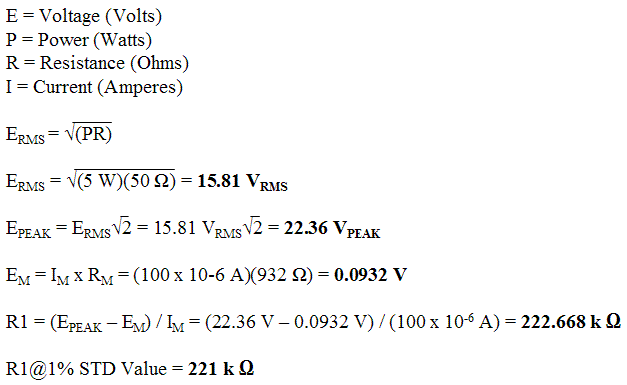
The calculations are as follows:

Calculations

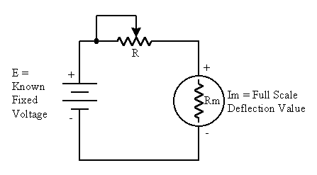
The internal resistance (Rm) can be found by constructing the simple circuit below and performing the following calculations:

Internal Meter Resistance

Adjust R until the meter reads it's full scale value. Be sure to start with R at it's maximum value to prevent damage to the meter. Solve the following equation to find the meter's internal resistance.

Internal Meter Resistance calculation

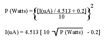
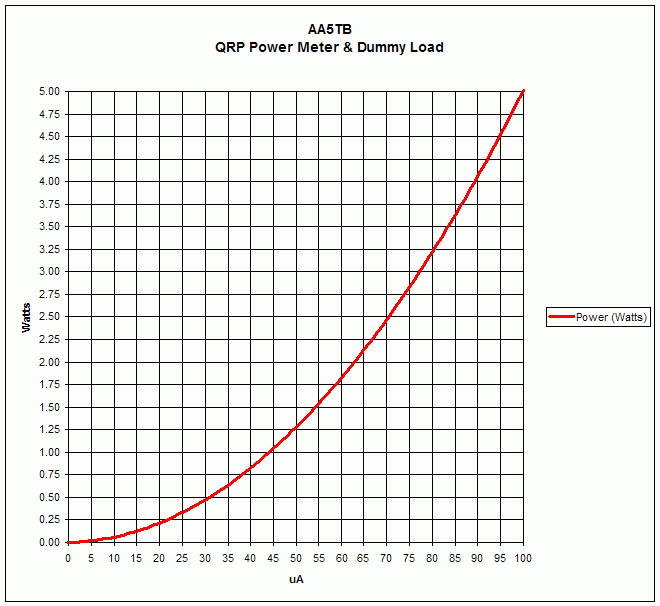
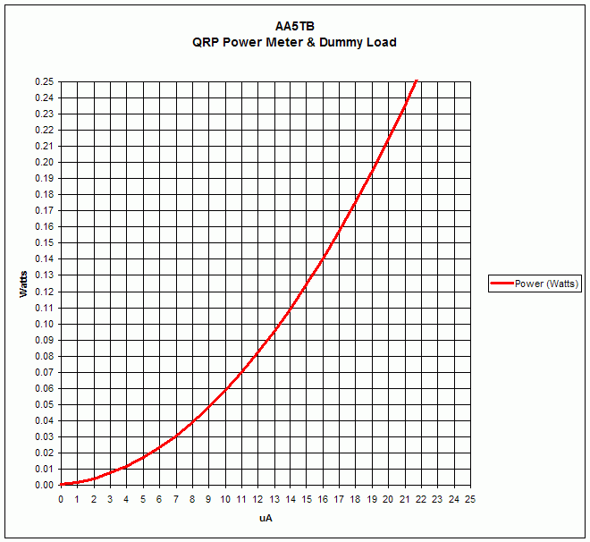
The formulae below are to convert the reading on the microampere meter to watts and back. Please note that the possible error caused by the diode's nonlinear response below about 100 mW has been ignored. The scale in the region of tens of milliwatts could be calibrated against a known calibrated power meter or signal source if desired. For more information regarding the very low power measurements with a diode detector you may want to check out "Square Law Diode Detectors in 50 ohm Systems" presented by Glen, VE3DNL.

Power Calculations

Current to QRP Power Conversion Chart

Current to QRPp Power Conversion Chart