Steve Yates - AA5TB
For years I've thrown together simple antenna tuners to get me on the air when needed. Whenever I would go to a sidewalk sale or hamfest I would pick up any components that might someday come in handy to make an antenna tuner. Commercial antenna tuners are very expensive and often of questionable quality. They are so very simple to make that I find it hard to justify purchasing a store bought unit. I realize that good antenna tuner components can be quite expensive when purchased new if you are even lucky enough to find a supplier. If you are not in a hurry all of the necessary components can be found used for very reasonable prices.
There is nothing special about the antenna tuner described on this page. It is a simple T-network and I have found that it can match any unbalanced antenna system I've ever put on it. I've always used PI-networks but component values can become unwieldy at the lower frequencies for such a network. Below are some more photos of my T-network.
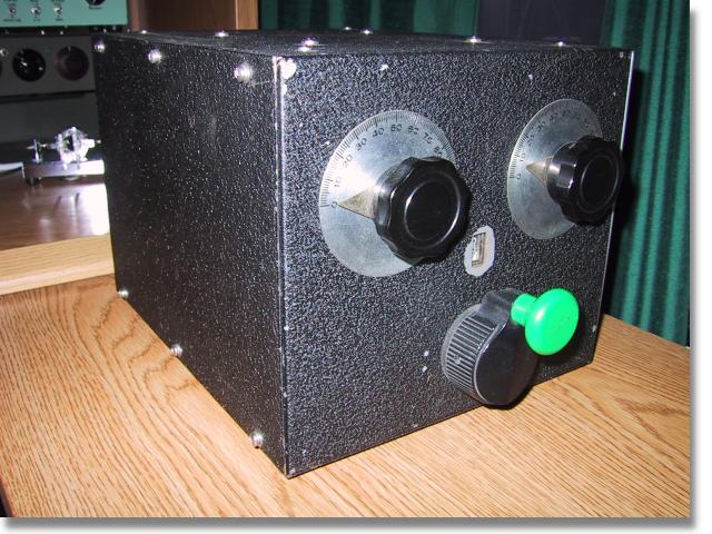
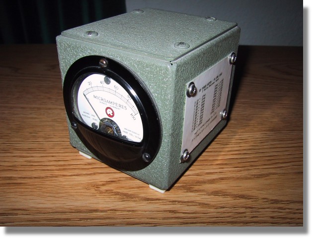
Front View
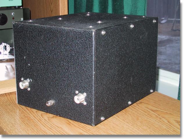
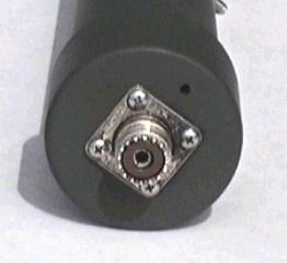
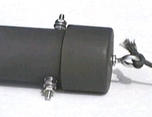
Rear View
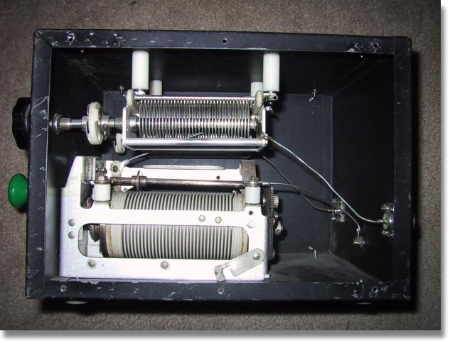
Inside View
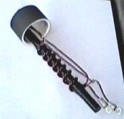
The components were all found on the surplus market and even though it looks very old it's really only a few years old. The metal enclosure is probably 50 years old even though it had never been used when I purchased it at a sidewalk sale. The roller inductor is silver plated and incorporates a very good turns counter. It is WWII surplus and I had been saving it ever since I came across it as a kid. The two capacitors are 500 pF each and I removed them out of a defunct automatic antenna tuner that was once used at a shore station for ship to shore communications. I purchased all of the insulators from a local surplus outlet. Even the knobs and dial plates are ancient surplus. After all is said and done, I have about $10 invested in this tuner but to purchase one of similar quality the price would probably be about $300.
I don't have plans for you to follow in order to replicate this antenna tuner but as you can see via the schematic it is very simple. I would suggest obtaining the components first and then design everything around them. Use short, fat conductors if possible to interconnect the components. Ther required capacitor plate spacing is determined by the transmitter power and the impedances involved. For 100 W or less the plate spacing of most available air-variable capacitors is probably adequate. The capacitors that I used here have a maximum capacitance value of 500pF each but I probably could have gotten by with 250 pF units. For the inductor try for around 25 µH if you plan to use the tuner on 80 m and maybe 160 m. The larger the inductor's conductor, the better. If you can't find a roller inductor then a tapped inductor can easily be made assuming an adequate switch can be obtained. Of course for simple open-air designs, a wire and alligator clip will suffice.
If the power you plan on using is at QRP levels, say less then 5 W, then the components can be greatly reduced in size. The polyvaricons that are often found in less expensive AM radios can be used for the capacitors and a small tapped coil wound on a toroid will suffice for the inductor. It should be noted however, that the efficiency of this antenna tuner is inversely related to the losses in the inductor. Therefore, even though a small inductor will not burn up at QRP levels, a dB of loss is a dB of loss at any power. What I am getting at is that at some impedance ratios, the RF currents in the coil can become relatively high. In these cases the losses within the inductor can become high unless care is taken to keep the Q of the coil high. This can be done by making the inductor out of the largest conductor possible and by making sure any contact resistance, such as the alligator clip, is kept at a minimum. It should be noted however, that this contact resistance will usually swamp out the RF resistance of the conductor. In other words, if you are using an el cheapo alligator clip or tap switch, there isn't too much sense in going to a 00 AWG conductor ;-)
I only created this page to hopefully encourage others to try and build their own antenna tuners instead spending good ham radio budget on an expensive commercial tuner. I apologize for not having exact instructions but this is an easy project to do on your own with the components that you have available.